Some Known Questions About Wedge Barriers.
Wiki Article
Excitement About Wedge Barriers
The springtime pole 58 is combined to a cam(e. g., camera 80 shown in FIG. 4) of the lifting device 50. The springtimes 60 disposed regarding the spring pole 58 are kept in compression by springtime supports 62, consisting of a dealt with springtime support 64. That is, the set springtime support 64 is repaired about the foundation 14 et cetera of the bather 10.
A Biased View of Wedge Barriers
The staying force used to the cam webcam deploy release wedge plate 16 may might provided by an electromechanical actuator 84 or other actuator. The springtime assembly 54 and the actuator 84(e. Wedge Barriers. g., electromechanical actuator)may operate with each other to translate the cam and lift the wedge plate 16.
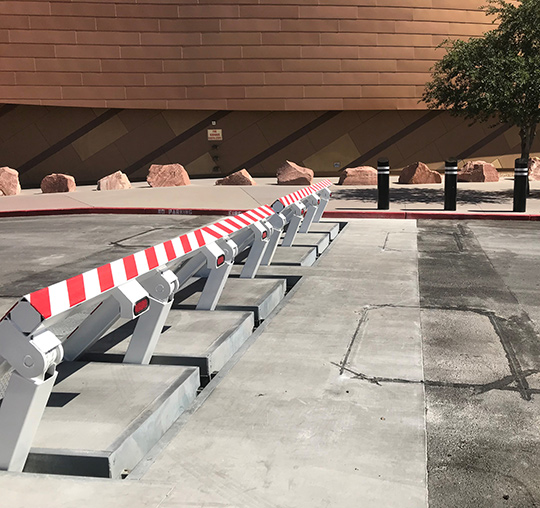
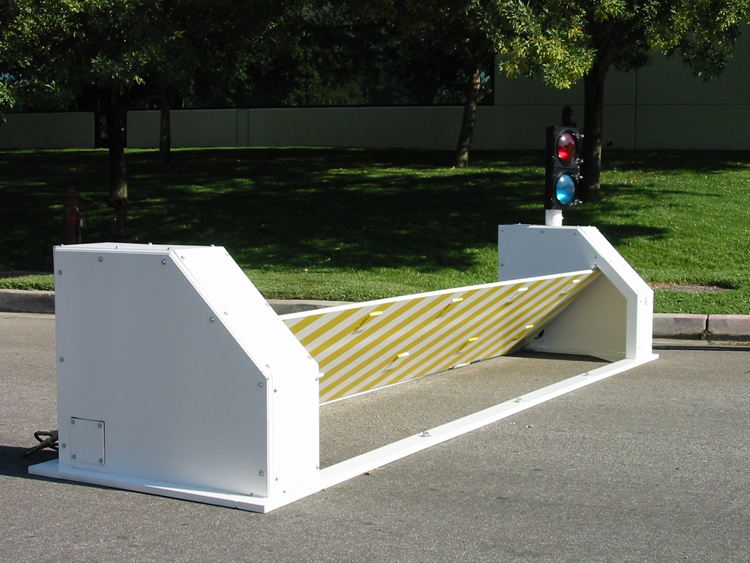
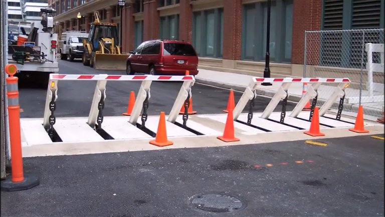
As stated over, the spring assembly 54 puts in a constant pressure on the web cam, while the electromechanical actuator may be controlled to apply a variable force on the webcam, consequently enabling the lifting and lowering( i. e., releasing and retracting )of the wedge plate 16. In specific embodiments, the consistent pressure used by the spring assembly 54 may be adjustable. g., electromechanical actuator) is handicapped. As will be appreciated, the springtime setting up 54 might be covered and shielded from particles or various other components by a cover plate(e. g., cover plate 68 revealed in FIG. 4) that might be considerably flush with the elevated surface 38 of the foundation 14. As pointed out over, in the deployed position, the wedge plate 16 serves to block access or traveling past the barrier 10. The barrier 10(e. g., the wedge plate 16 )may obstruct pedestrians or lorries from accessing a building or path. As find out this here discussed over, the obstacle 10 is connected to the anchor 30 protected within the structure 14,
front braces 71. Consequently, the link settings up 72 might pivot and turn to make it possible for the collapse and expansion of the linkage assemblies 72 during retraction and deployment of the bather 10. The affiliation settings up 72 cause movement of the wedge plate 16 to be restricted. As an copyrightple, if an automobile is traveling in the direction of the released wedge plate 16(e. For copyrightple, in one situation, the go right here security legs 86 might be prolonged duringmaintenance of the obstacle 10. When the safety and security legs 86 are deployed, the security legs 86 support the weight of the wedge plate 16 against the surface 12. Because of this, the lifting device 50 may be shut off, serviced, gotten rid of, changed, etc. FIG. 5 is partial perspective view of a personification of the surface-mounted wedge-style barrier 10, illustrating the cam 80 and the cam surface areas 82 of the lifting mechanism 50. Especially, two cam surface areas 82, which are described as reduced camera surfaces 83, are positioned listed below the webcam 80. The reduced web cam surfaces 83 might be dealt with to the surface area 12 (e. As an copyrightple, the lower web cam check out here surface areas 83 and the installing plate 85 may form a single item that is safeguarded to the anchor 30 by bolts or various other mechanical fasteners. Additionally, two webcam surfaces 82, which are described as upper cam surface areas 87, are placed above the cam 80 and coupled to (e. In various other embodiments, interfering layers or plates might be placed between the surface 12 and the reduced webcam surfaces 83 and/or the wedge plate 16 and the upper camera surfaces 87 As discussed over, the cam 80 equates along the cam surface areas 82 when the wedge plate 16 is lifted from the withdrawed placement to the released setting. Additionally, as stated over, the spring assembly 54 (see FIG. 3 )may offer a pressure acting on the web cam 80 in the direction 102 via springtime rod 58, which may decrease the pressure the electromechanical actuator 84 is called for to relate to the camera 80 in order to activate and lift the wedge plate 16. 1 )to the released setting(see FIG. 4). As revealed, the webcam 80 consists of track wheels 104(e. g., rollers), which call and translate along the web cam surface areas 82 throughout procedure.
Report this wiki page